Quantcast
Channel: From the Trenches with Autodesk Inventor
Viewing all 61 articles
Browse latest View live

Creating a Basic iLogic Rule with an Event Trigger

$
0
0


Issue:
You've found some iLogic code online, but you're not sure how to create a simple rule or have it trigger on a save event. You've found the iLogic tutorials on line, but don't have the time to go through them right now. You really just want to know how to create a simple rule and get it working.

Solution:
Here are some basics to get you going, using some simple example code to update the creation date and author iProperties, as described at this link.

Here is the iLogic Code you'll use:

'set Author iproperty to match the system user name
iProperties.Value("Summary", "Author") = ThisApplication.GeneralOptions.UserName
'set the Creattion Date iproperty to the current date
iProperties.Value("Project", "Creation Date") = Now
'update the file
iLogicVb.UpdateWhenDone = True


To use this code first create an iLogic Rule:
  1. On the ribbon, click Manage tab > iLogic panel > Add Rule button.
  2. Name the new rule Name-Date.
  3. In the rule text area of the Edit Rule dialog box, simply paste in the code from above.
  4. Click OK to save this new rule.
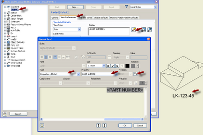
Next you need to have a couple of text fields that read the iProperties (you'd likely create these text objects in your title block, but for now just create some simple text on your drawing to test this first).
  1. On the ribbon, click Annotate tab > Text panel > Text button.
  2. Click on screen to place the text
  3. In the Format Text dialog box select the Type pull down and choose Properties - Model from the list.
  4. Then select the Property pull down and choose Creation Date from the list.
  5. Then click the Add Text Parameter button (looks like and X with an arrow) to "push" the field to the text box.  
  6. Click OK to create the text.
  7. Repeat these steps for the Author iProperty
Next set the rule to trigger when the file is saved.
  1. On the ribbon, click Manage tab > iLogic panel > Event Triggers button. A dialog box displays the list of available events.
  2. Click the Before Save Document event in the list.
  3. Click Select Rules, or right-click and choose Select Rules from the context menu.
  4. Place a check mark next to the Name-Date rule.
  5. Click OK.
  6. Click OK to close the event list.
Now whenever this file is saved the date and name text fields are updated.
 
Note:
You might also be interested in this post from the guys at the Being Inventive blog:
http://beinginventive.typepad.com/being-inventive/2011/07/plot-date-stamp-in-title-block.html

And this article from Paul Munford:
http://www.augi.com/library/playing-by-the-ilogic-rules 


And this article from Steve Bedder:
http://autodeskmfg.typepad.com/blog/2012/01/working-with-external-ilogic-rules.html


Set Your Drawing View Labels to Use the Model Part Number

$
0
0
Issue:
You'd prefer your view labels to use the model part number (or some other file property) rather than the default "View1", "View2", and so on. Re-naming the view labels manually is tedious and error prone. 


Solution:
You can change the view label default to use an iProperty from the model using these steps:
  • Open a drawing file
  • Go to the Manage tab
  • Click the Styles and Standards button
  • Click the Standard to work with from the top of the tree on the left pane
  • Activate the View Preferences tab in the right pane
  • Click the Edit button for Display field
  • Set the Type drop down to Properties-Model
  • Set the Properties drop down to Part Number (or something else)
  • Click the Add Text Parameter button to add this property to your view label

You can click the image below to enlarge it and see the picks and clicks.

Click to Enlarge


Here is a bit of iLogic Code to set the view name and browser node to the model part number also:


'start of ilogic code
Dim oApp As Application: oApp = ThisApplication
Dim oDoc As DrawingDocument:  oDoc = oApp.ActiveDocument

Dim oSheets As Sheets
Dim oSheet As Sheet
Dim oViews As DrawingViews
Dim oView As DrawingView

oSheets = oDoc.Sheets

For Each oSheet In oSheets
oViews = oSheet.DrawingViews
                For Each oView In oViews
                oModelName = _
                oView.ReferencedDocumentDescriptor.ReferencedDocument.DisplayName
                oPartNumber = iProperties.Value(oModelName, "Project", "Part Number")
            oView.Name = oPartNumber
                Next
Next
'end of ilogic code


Update:
By request here is a rule that adds a custom iProperty to the view label with a dash separator.


'start of ilogic code
Dim oDoc As DrawingDocument:  oDoc = ThisDoc.Document

Dim oSheets As Sheets
Dim oSheet As Sheet
Dim oViews As DrawingViews
Dim oView As DrawingView

oSheets = oDoc.Sheets

For Each oSheet In oSheets
oViews = oSheet.DrawingViews
                For Each oView In oViews
                'capture the current view label
                ViewLabel = oView.Name
                oModelName = _
                oView.ReferencedDocumentDescriptor.ReferencedDocument.DisplayName
                Try
            o_iProp = iProperties.Value(oModelName, "Custom", "My_iProp")        
            'add the the iProperty to the current view label, with a dash separator
                oView.Name = ViewLabel & " - "& o_iProp
            Catch
            'do nothing if error
                End Try
            Next
Next

'end of ilogic code


iLogic to Rename All Solid Bodies

$
0
0
Issue:
You've created a multi-body solid model with the intent to use the Make Components tool to write out each solid as a new part file. This works fine, but you find yourself wishing there was an easier way to tag each solid with a new name based on a prefix and a series number. For instance, you'd like to name each solid in a part file called 45-723 as such: 45-723_01, 45-723_02, 45-723_03, etc.


Issue:
You can use this iLogic rule to quickly rename the solid bodies for you. In this rule we first look for a custom iProperty named "Prefix" and create it if it is not present. Then we write the part number to the custom iProperty if it is found to be empty. Then the rule uses the value of the custom iProperty named "Prefix" in an input box to query the user for the prefix:


The user can change the prefix at this point or accept the existing one. When we press the OK button the rule renames each solid body using the prefix and an increment number, adding a leading zero for each number less than 10.

Thanks to Barbara Han for the original code I used for this rule.


'------- start of ilogic ------
'check for custom iProperty and add it if not found
Dim prefix As String = "Prefix"
customPropertySet = ThisDoc.Document.PropertySets.Item _
("Inventor User Defined Properties")

Try
         prop= customPropertySet.Item(prefix)
Catch
      ' Assume error means not found
            customPropertySet.Add("", prefix)
End Try

'write the part number to the Prefix iProperty if it is empty
if iProperties.Value("Custom", "Prefix") = ""Then
iProperties.Value("Custom", "Prefix") = iProperties.Value("Project", "Part Number") & "_"
else
end if

'check that this active document is a part file   
Dim partDoc As PartDocument
If ThisApplication.ActiveDocument.DocumentType <> kPartDocumentObject Then
MessageBox.Show ("Please open a part document", "iLogic")
End If

'define the active document
partDoc = ThisApplication.ActiveDocument
Dim solid As SurfaceBody
Dim i As Integer

'get input from user
prefix = InputBox("Enter a prefix for the solid body names", "iLogic", iProperties.Value("Custom", "Prefix"))

'write input back to custom iProperty
iProperties.Value("Custom", "Prefix") = prefix
i = 1
'rename all solid bodies incrementing suffix
For Each solid In partDoc.ComponentDefinition.SurfaceBodies
solid.Name = prefix + IIf(i < 10, "0"+ CStr(i), CStr(i))
i = i + 1
Next
------- end of ilogic ------

iLogic to Select all of the Closed Profiles Found in a Sketch

$
0
0
Issue:
You find yourself needing to select a large number of closed profiles in a sketch of a logo or something similar. This is quite tedious and because you reuse the sketch over and over, you find yourself wishing you had a better way to do this.

Here is an example of a logo that was copied from AutoCAD and placed in an Inventor sketch block. It's a bit tedious to select all of these profiles each time the logo is used on a laser engraved part.


Solution:
You can use the following iLogic rule to select all of the closed profiles found in the sketch, and create an Extrude feature from them.


'----start of ilogic -------
If Typeof ThisApplication.ActiveEditObject Is Sketch Then
'Do nothing
Else
MessageBox.Show("Activate a Sketch First then Run this Rule", "ilogic")
Return
End If

Dim oPartDoc As PartDocument
oPartDoc = ThisApplication.ActiveDocument

Dim oCompDef As PartComponentDefinition
oCompDef = oPartDoc.ComponentDefinition

Dim oSketch As PlanarSketch
oSketch = ThisApplication.ActiveEditObject

' Create a profile.
Dim oProfile As Profile
On Error Goto NoProfile
oProfile = oSketch.Profiles.AddForSolid

'get user input
oDistance = InputBox("Enter Extrude Distance", "iLogic", "10 mm")
oDirection  = InputRadioBox("Select Extrude Direction", "Up (+)", "Down (-)", True, Title := "iLogic")
oJoinOrCut  = InputRadioBox("Select Extrude Solution", "Join", "Cut", True, Title := "iLogic")

If oDirection = True then
oDirection = kPositiveExtentDirection
Else
oDirection = kNegativeExtentDirection
End if

If oJoinOrCut = True then
oJoinOrCut = kJoinOperation
Else
oJoinOrCut = kCutOperation
End if

' Create an extrusion
Dim oExtrude As ExtrudeFeature
On Error Goto NoExtrude
oExtrude = oCompDef.Features.ExtrudeFeatures.AddByDistanceExtent( _
oProfile, oDistance, oDirection, oJoinOrCut)

ThisApplication.CommandManager.ControlDefinitions.Item("FinishSketch").Execute

iLogicVb.UpdateWhenDone = True

exit sub

NoProfile:
MessageBox.Show("No closed profile found", "iLogic")
Return

NoExtrude:
MessageBox.Show("No extrusion created, check your inputs.", "iLogic")
Return
'----end of ilogic -------


 ---------------------------------------------------------------------------------------------------------------------
Update ( 8/21/2012 ):

By request here is another version of this rule that automatically cuts through all:

'----start of ilogic -------
If Typeof ThisApplication.ActiveEditObject Is Sketch Then
'Do nothing
Else
MessageBox.Show("Activate a Sketch First then Run this Rule", "ilogic")
Return
End If

Dim oPartDoc As PartDocument
oPartDoc = ThisApplication.ActiveDocument

Dim oCompDef As PartComponentDefinition
oCompDef = oPartDoc.ComponentDefinition

Dim oSketch As PlanarSketch
oSketch = ThisApplication.ActiveEditObject

' Create a profile.
Dim oProfile As Profile
On Error Goto NoProfile
oProfile = oSketch.Profiles.AddForSolid

'set direction
oDirection  = kSymmetricExtentDirection
'set operation
oJoinOrCut  = kCutOperation

' Create an extrusion
Dim oExtrude As ExtrudeFeature
On Error Goto NoExtrude
oExtrude = oCompDef.Features.ExtrudeFeatures.AddByThroughAllExtent( _
oProfile, oDirection, oJoinOrCut)

ThisApplication.CommandManager.ControlDefinitions.Item("FinishSketch").Execute

iLogicVb.UpdateWhenDone = True

exit sub

NoProfile:
MessageBox.Show("No closed profile found", "iLogic")
Return

NoExtrude:
MessageBox.Show("No extrusion created, check your inputs.", "iLogic")
Return
'----end of ilogic ------- 


------------------------------------------------------------------------------------------------------------------------------------------
Update ( 8/21/2012 ):

By request here is another version of this rule that extrudes using the To Next method:


'----start of ilogic -------
If Typeof ThisApplication.ActiveEditObject Is Sketch Then
'Do nothing
Else
MessageBox.Show("Activate a Sketch First then Run this Rule", "ilogic")
Return
End If

Dim oPartDoc As PartDocument
oPartDoc = ThisApplication.ActiveDocument

Dim oCompDef As PartComponentDefinition
oCompDef = oPartDoc.ComponentDefinition

Dim oSketch As PlanarSketch
oSketch = ThisApplication.ActiveEditObject

' Create a profile.
Dim oProfile As Profile
On Error Goto NoProfile
oProfile = oSketch.Profiles.AddForSolid

oDirection  = InputRadioBox("Select Extrude Direction", "Up (+)", "Down (-)", True, Title := "iLogic")
oJoinOrCut  = InputRadioBox("Select Extrude Solution", "Join", "Cut", True, Title := "iLogic")

If oDirection = True then
oDirection = kPositiveExtentDirection
Else
oDirection = kNegativeExtentDirection
End if

If oJoinOrCut = True then
oJoinOrCut = kJoinOperation
Else
oJoinOrCut = kCutOperation
End if

Dim oTerminator As SurfaceBody
oTerminator = oCompDef.SurfaceBodies(1)

' Create an extrusion
Dim oExtrude As ExtrudeFeature
On Error Goto NoExtrude
oExtrude = oCompDef.Features.ExtrudeFeatures.AddByToNextExtent( _
oProfile, oDirection, oTerminator, oJoinOrCut)

ThisApplication.CommandManager.ControlDefinitions.Item("FinishSketch").Execute
iLogicVb.UpdateWhenDone = True

exit sub

NoProfile:
MessageBox.Show("No closed profile found", "iLogic")
Return

NoExtrude:
MessageBox.Show("No extrusion created, check your inputs.", "iLogic")
Return
'----end of ilogic -------


Working With Unconstrained Imported Assembly Components

$
0
0


Issue:
You've found a great 3D model on the web that you want to use in Inventor. It was originally created in some other 3D design software, but you were able to import it into Inventor. The problem is that the parts come in unconstrained and can move all over the place. Is there an option to import models from other software and keep the assembly constraints?

Solution:
There is no option to import the assembly constraints, but most likely you won't need to apply constraints to all of the parts because they have been imported in the correct orientation and location. Instead you can just ground all of the parts in place so that they will not move, and then un-ground and apply assembly constraints to just the parts that need to move or that you need to edit.

If the assembly has a lot of moving parts that need assembly constraints, you can un-ground and constrain one part at a time to keep everything from moving on you.

Here is a quick iLogic rule that will ground all components in place also.

'start of ilogic code
' set a reference to the assembly component definintion.
' This assumes an assembly document is open.
Dim oAsmCompDef As AssemblyComponentDefinition
oAsmCompDef = ThisApplication.ActiveDocument.ComponentDefinition

'set the Master LOD active
Dim oLODRep As LevelofDetailRepresentation
oLODRep = oAsmCompDef.RepresentationsManager.LevelOfDetailRepresentations.Item("Master")
oLODRep.Activate

 'Iterate through all of the occurrences and ground them.
Dim oOccurrence As ComponentOccurrence
For Each oOccurrence In oAsmCompDef.Occurrences
'check for and skip virtual components
If Not TypeOf oOccurrence.Definition Is VirtualComponentDefinition Then
oOccurrence.Grounded = True
else
end if
Next
'end of ilogic code

ilogic Rule To Change Units Of Measure

$
0
0


Issue:
You've created some of your parts in inches and others in millimeters, but now you'd like to convert them all to be the same. Is there a quick way to do this without having to open each file go to the Tools tab > Document Settings button > Unitstab?


Solution:
Here's an ilogic rule that can be run in an assembly or a part file that will set the units of measure. In this rule the length and mass units are being set. Set this up as an external iLogic rule to have it available for use in all of your model files.

You can use these links to learn more about creating iLogic rules:


'------- start of ilogic ------
question = MessageBox.Show("Are you sure you want to change the units of measure?", _
"iLogic",MessageBoxButtons.YesNo)

if question = vbno then
Return
Else

            'get input from user
                oUnit = InputRadioBox("Select a units of measure type", "Metric", "Imperial", True, "ilogic")
           
            'create precision value list
                oPrecisionArray = new string(){0, 1, 2, 3, 4, 5}

                'get input from user
                oPrecision = InputListBox("Select the number of decimal places to use for the units of length display.",  _
                oPrecisionArray, 3, "iLogic", "Decimal Places ")
           
            'example UnitsTypeEnum Enumerators
                'kCentimeterLengthUnits = 11268
                'kMillimeterLengthUnits = 11269
                'kInchLengthUnits = 11272
               
                'kKilogramMassUnits = 11283
                'kGramMassUnits = 11284
                'kLbMassMassUnits = 11286
               
                                If oUnit = True then
                        'set to millimeter
                                oUOM_1 = 11269
                        'set to kilogram
                                oUOM_2 = 11283
                        Else
                        'set to inch
                                oUOM_1 = 11272
                        'set to pounds mass
                                oUOM_2 = 11286                        
                        End if

            'Define the open document
                Dim openDoc As Document
                openDoc = ThisDoc.Document
            'set length units for the top level assembly
                openDoc.unitsofmeasure.LengthUnits = oUOM_1
                'set mass units for the top level assembly
                openDoc.unitsofmeasure.MassUnits = oUOM_2
                'set precision
                openDoc.unitsofmeasure.LengthDisplayPrecision = oPrecision
               
                'Look at all of the files referenced in the open document
                Dim docFile As Document
                For Each docFile In openDoc.AllReferencedDocuments                
                                'format  file name                   
                                Dim FNamePos As Long
                                FNamePos = InStrRev(docFile.FullFileName, "\", -1)                        
                        Dim docFName As String 
                        docFName = Right(docFile.FullFileName, Len(docFile.FullFileName) - FNamePos)      
                        'set length units
                                docFile.unitsofmeasure.LengthUnits = oUOM_1
                                'set mass units
                                docFile.unitsofmeasure.MassUnits = oUOM_2
                                'set precision
                                docFile.unitsofmeasure.LengthDisplayPrecision = oPrecision
                                'rebuild to update the display
                                docFile.Rebuild
                Next    
End if
'update all
iLogicVb.UpdateWhenDone = True

'------- end of ilogic ------

Create a New Excel File with iLogic

$
0
0


Issue:
You have the need to write out information from Inventor to a spreadsheet. But you're not sure how to create a create a new Excel.

Solution:
Here is a quick iLogic rule that will look for an existing Excel file and then create one if it is not found.


'------ start of iLogic ----------------------------------------------------------

'define the file to create/open
myXLS_File = "C:\Temp\Best_Excel_File_Ever.xls"

‘get the Inventor user name from the Inventor Options
myName= ThisApplication.GeneralOptions.UserName

'define Excel Application object
excelApp = CreateObject("Excel.Application")
'set Excel to run visibly, change to false if you want to run it invisibly
excelApp.Visible = True
'suppress prompts (such as the compatibility checker)
excelApp.DisplayAlerts = false

'check for existing file
If Dir(myXLS_File) <> ""Then
'workbook exists, open it
excelWorkbook = excelApp.Workbooks.Open(myXLS_File)
'set the first sheet active
excelSheet = excelWorkbook.Worksheets(1).activate
Else
'workbook does NOT exist, so create a new one using the default template
excelWorkbook = excelApp.Workbooks.Add
' or use this syntax to specify a template to use
'excelWorkbook =  excelApp.Workbooks.Add (Template: = "C:\Temp\Best_Excel_Template_Ever.xlt")
End if

'Insert data into Excel.
With excelApp
                .Range("A1").Select
            .ActiveCell.Value = "Hello, "& myName
End With  

'set all of the columns to autofit
excelApp.Columns.AutoFit  
'save the file
excelWorkbook.SaveAs (myXLS_File)

''close the workbook and the Excel Application
''uncomment if you want to close the xls file at the end
'excelWorkbook.Close
'excelApp.Quit
'excelApp = Nothing
'------ end of iLogic ----------------------------------------------------------

iLogic and the Inventor Project File

$
0
0


Issue:
You want to reference the current Inventor Project file within an iLogic rule.

Solution:
Here is a quick iLogic snippet that will demonstrate how to work with the Project file and path. In this example the project name, project file name, project path, and the full project path and file name are written to a message box.


'------ start of iLogic ----------------------------------------------------------

Dim IPJ as String
Dim IPJ_Name as String
Dim IPJ_Path as String
Dim FNamePos As Long
'set a reference to the FileLocations object.
IPJ = ThisApplication.FileLocations.FileLocationsFile
'get the location of the last backslash seperator
FNamePos = InStrRev(IPJ, "\", -1)    
'get the project file name with the file extension
IPJ_Name = Right(IPJ, Len(IPJ) - FNamePos)
'get the project name (without extension)
IPJ_ShortName = Left(IPJ_Name, Len(IPJ_Name) - 4)
'get the path of the folder containing the project file
IPJ_Folder_Location = Left(IPJ, Len(IPJ) - Len(IPJ_Name))

MessageBox.Show("Project Name: "& IPJ_ShortName _
& vblf & "Project File Name: "& IPJ_Name _
& vblf & "Project Path: "& IPJ_Folder_Location _
& vblf & "Project Path and File Name: "& IPJ, "iLogic")

'------ end of iLogic ----------------------------------------------------------


******** Update (01/09/2013) ********
Here's some code to work with the project WorkSpace:

myWorkSpace = ThisApplication.FileLocations.Workspace
MessageBox.Show("WorkSpace Path:  "& myWorkSpace, "iLogic")


 And here's another snippet to work with project Workgroups:


Dim asNames() As String = {}
Dim asPaths() As String = {}
Dim iNumWorkgroups As Long
ThisApplication.FileLocations.Workgroups(iNumWorkgroups, asNames, asPaths)

If iNumWorkgroups = 0 Then
MessageBox.Show("No Workgroups are defined in the current project.", "iLogic")
Else
          i = 0
          Do until i = iNumWorkgroups
            wGName = asNames(i)
          wGPath = asPaths(i)
          MessageBox.Show("WorkGroup Name: "& wGName _
            & vblf & "WorkGroup Path: "& wGPath , "iLogic")
          i = i + 1
          Loop
End If


iLogic: Get File Information for the Selected Component

$
0
0


Issue:
You want to find the file name or path of a selected component in your iLogic rule.

Solution:
Here is a quick iLogic snippet that will demonstrate how to work with the selected component file and path. In this example the file name, file name without extension, file path, and the full path and file name are written to a message box.


'------------ start of ilogic--------------------
'get currently selected component
Dim oOccurrence as ComponentOccurrence
Try
  oOccurrence = ThisDoc.Document.SelectSet.Item(1)
Catch
  MessageBox.Show("Please select a component before running this rule.", "iLogic")
  Return
End Try

Dim doc As Document
Dim CurFileName As String

'set the selected item
oOccurrence = ThisApplication.ActiveDocument.SelectSet.Item(1)

'get the selected item document occurrence name
doc = oOccurrence.Definition.Document

'get the path and file name of the selected item
CurFileName = doc.FullFileName

'defines backslash as the subdirectory separator
Dim strCharSep As String = System.IO.Path.DirectorySeparatorChar

'find the postion of the last backslash in the path
FNamePos = InStrRev(CurFileName, "\", -1)   
'get the file name with the file extension
Name = Right(CurFileName, Len(CurFileName) - FNamePos)
'get the file name (without extension)
ShortName = Left(Name, Len(Name) - 4)
'get the path of the folder containing the file
Folder_Location = Left(CurFileName, Len(CurFileName) - Len(Name))

MessageBox.Show("File Name: "& Name _
& vblf & "File Name without extension: "& ShortName _
& vblf & "File Path: "& Folder_Location _
& vblf & "Path and File Name: "& CurFileName, "iLogic")
'------------ end of ilogic--------------------

Disable Automatic PDF Display

$
0
0


Issue:
When you use Save As> Save Copy As> PDF, or Export> PDF,  Inventor always opens the PDF viewer to show the PDF file after it is published. This can be a bother, due to the delay caused by waiting for the PDF viewer to open each time. Is there a way to change this so that the PDF does not automatically open after it is published?

Solution:
As odd as it sounds, this is controlled in the publish options of the DWF file. 

Go to Export> Export to DWF and un-check the Display Published File in Vieweroption found at the bottom of the Generaltab. This option controls the PDF viewer as well as the DWF. With this option unchecked the PDF will not open automatically after it is published.

iLogic: Virtual Components

$
0
0


Issue:
You have some iLogic code that iterates through all of the components in an assembly and does some something with the file for each. However, if the assembly contains a virtual component then the iLogic code fails. Is there a way to skip over virtual components when encountered?

Solution:
Here is an iLogic snippet that demonstrates this using If Not TypeOf. In this simple example the iLogic rule simply displays the occurrence name if the occurrence is not a virtual component.


'------------ start of ilogic--------------------
' set a reference to the assembly component definintion.
' This assumes an assembly document is open.
Dim oAsmCompDef As AssemblyComponentDefinition
oAsmCompDef = ThisApplication.ActiveDocument.ComponentDefinition

'Iterate through all of the occurrences
Dim oOccurrence As ComponentOccurrence
For Each oOccurrence In oAsmCompDef.Occurrences
'check for and skip virtual components
'(in case a virtual component trips things up)
If Not TypeOf oOccurrence.Definition Is VirtualComponentDefinition Then
'Show occurrence name In the message box body
MessageBox.Show(oOccurrence.Name, "iLogic")
Else
End If
Next
'------------ end of ilogic--------------------

Inventor Background Color as White: Improved

$
0
0

Issue:
You'd like to use a solid white back ground in Inventor because it allows you to take quick screen captures for use in illustrations for a variety of publications (examples:  how to videos, company  standards documentation, build procedures, catalogs, and so on).

A screen capture taken while using a solid white background.

The problem however, is that when you use the Presentation color scheme, all of the projected geometry is yellow. Working with yellow lines on a white background makes these projected sketch lines difficult to see.

 
Additionally, if you use Inventor during a presentation or training, the white background used in the Presentation color scheme often shows up best, but again the yellow projected lines makes it difficult to work with, particularly with some projectors.

Is there a way to change the projected line color?

Solution:
Rather than changing the projected line color used in the Presentation color scheme, you can use one of the other color schemes, and use a solid white background image. To do so, go to the Tools tab > Application Options button > Colors tab,  and then change the Background setting to Background Image. Then use the browse button for the File Name setting to browse out and select a previously saved image file. 


I prefer to use the Sky color scheme (it uses green lines for the projected geometry color), with a file called Blank White.jpg. I created the file called Blank White.jpg using Microsoft Paint and saved it to the Inventor Backgrounds directory.
 
 Give this a try and I think you'll find that it works much better than the yellow on white of the Presentation color scheme.

iLogic: Adding a Save As Dialog Box

$
0
0


Issue:
You'd like to present the user with a Save As dialog box that will allow them to browse for a folder during the execution of your iLogic rule. However, the examples in the iLogic snippets all use a predefined or hard coded folder path. Is there a way to present a Save As dialog box, so the iLogic rule can be more dynamic?

Solution:
Here's a quick snippet that presents a Save dialog box, allowing a destination folder to be selected:


'define the active document
oDoc = ThisDoc.Document
'create a file dialog box
Dim oFileDlg As inventor.FileDialog = Nothing
InventorVb.Application.CreateFileDialog(oFileDlg)

'check file type and set dialog filter
If oDoc.DocumentType = kPartDocumentObject Then
oFileDlg.Filter = "Autodesk Inventor Part Files (*.ipt)|*.ipt"
Else if oDoc.DocumentType = kAssemblyDocumentObject Then
oFileDlg.Filter = "Autodesk Inventor Assembly Files (*.iam)|*.iam"
Else if oDoc.DocumentType = kDrawingDocumentObject Then
oFileDlg.Filter = "Autodesk Inventor Drawing Files (*.idw)|*.idw"
End If

'set the directory to open the dialog at
oFileDlg.InitialDirectory = ThisDoc.WorkspacePath()
'set the file name string to use in the input box
oFileDlg.FileName = iProperties.Value("Project", "Part Number")

'work with an error created by the user backing out of the save
oFileDlg.CancelError = True
On Error Resume Next
'specify the file dialog as a save dialog (rather than a open dialog)
oFileDlg.ShowSave()

'catch an empty string in the imput
If Err.Number <> 0 Then
MessageBox.Show("No File Saved.", "iLogic: Dialog Canceled")
ElseIf oFileDlg.FileName <> ""Then
MyFile = oFileDlg.FileName
'save the file
oDoc.SaveAs(MyFile, False) 'True = Save As Copy & False = Save As
End If

iLogic: Batch Output PDFs from an Assembly File

$
0
0
Issue:
You'd like to output a PDF file from the drawings of all the components found in an assembly file (if those components have a drawing file created), and you like also create a PDF of the top level assembly drawing as well. All of these PDFs should be written out to a single folder. Can this be done?

Solution:
Here's  an ilogic rule to batch output PDF files for each component in an assembly. This rule assumes that the component drawings share the same name and location of the component.

For example: C:\Temp\widget-450.ipt has a drawing: C:\Temp\widget-450.idw
If the drawing file is not found, then it simply moves on and looks at the next component.


This rule may not work for everyone, but it should provide a starting point from which it can be modified as needed. If you work with *.dwg files rather than *.idw files you can search and replace this code for idw and replace with dwg.

Here is the code in a *.txt file that can be downloaded as well:
http://forums.autodesk.com/autodesk/attachments/autodesk/78/455124/2/Batch%20PDFs.txt 


'define the active document as an assembly file
Dim oAsmDoc As AssemblyDocument
oAsmDoc = ThisApplication.ActiveDocument
oAsmName = Left(oAsmDoc.DisplayName, Len(oAsmDoc.DisplayName) -4)

'check that the active document is an assembly file
If ThisApplication.ActiveDocument.DocumentType <> kAssemblyDocumentObject Then
MessageBox.Show("Please run this rule from the assembly file.", "iLogic")
Exit Sub
End If

'get user input
RUsure = MessageBox.Show ( _
"This will create a PDF file for all of the asembly components that have drawings files."_
& vblf & "This rule expects that the drawing file shares the same name and location as the component."_
& vblf & ""_
& vblf & "Are you sure you want to create PDF Drawings for all of the assembly components?"_
& vblf & "This could take a while.", "iLogic  - Batch Output PDFs ",MessageBoxButtons.YesNo)

If RUsure = vbNo Then
Return
Else
End If

'- - - - - - - - - - - - -PDF setup - - - - - - - - - - - -
oPath = ThisDoc.Path
PDFAddIn = ThisApplication.ApplicationAddIns.ItemById("{0AC6FD96-2F4D-42CE-8BE0-8AEA580399E4}")
oContext = ThisApplication.TransientObjects.CreateTranslationContext
oContext.Type = IOMechanismEnum.kFileBrowseIOMechanism
oOptions = ThisApplication.TransientObjects.CreateNameValueMap
oDataMedium = ThisApplication.TransientObjects.CreateDataMedium

If PDFAddIn.HasSaveCopyAsOptions(oDataMedium, oContext, oOptions) Then
'oOptions.Value("All_Color_AS_Black") = 0
oOptions.Value("Remove_Line_Weights") = 1
oOptions.Value("Vector_Resolution") = 400
oOptions.Value("Sheet_Range") = Inventor.PrintRangeEnum.kPrintAllSheets
'oOptions.Value("Custom_Begin_Sheet") = 2
'oOptions.Value("Custom_End_Sheet") = 4
End If

'get PDF target folder path
oFolder = oPath & "\"& oAsmName & " PDF Files"

'Check for the PDF folder and create it if it does not exist
If Not System.IO.Directory.Exists(oFolder) Then
    System.IO.Directory.CreateDirectory(oFolder)
End If
'- - - - - - - - - - - - -

'- - - - - - - - - - - - -Component Drawings - - - - - - - - - - - -
'look at the files referenced by the assembly
Dim oRefDocs As DocumentsEnumerator
oRefDocs = oAsmDoc.AllReferencedDocuments
Dim oRefDoc As Document

'work the the drawing files for the referenced models
'this expects that the model has a drawing of the same path and name
For Each oRefDoc In oRefDocs
idwPathName = Left(oRefDoc.FullDocumentName, Len(oRefDoc.FullDocumentName) - 3) & "idw"
'check to see that the model has a drawing of the same path and name
If(System.IO.File.Exists(idwPathName)) Then
                        Dim oDrawDoc As DrawingDocument
                oDrawDoc = ThisApplication.Documents.Open(idwPathName, True)
            oFileName = Left(oRefDoc.DisplayName, Len(oRefDoc.DisplayName) -3)

            On error Resume Next ' if PDF exists and is open or read only, resume next
                 'Set the PDF target file name
                oDataMedium.FileName = oFolder & "\"& oFileName & "pdf"
                'Write out the PDF
                Call PDFAddIn.SaveCopyAs(oDrawDoc, oContext, oOptions, oDataMedium)
            'close the file
                oDrawDoc.Close
Else
'If the model has no drawing of the same path and name - do nothing
End If
Next
'- - - - - - - - - - - - -

'- - - - - - - - - - - - -Top Level Drawing - - - - - - - - - - - -
oAsmDrawing = ThisDoc.ChangeExtension(".idw")
oAsmDrawingDoc = ThisApplication.Documents.Open(oAsmDrawing, True)
oAsmDrawingName = Left(oAsmDrawingDoc.DisplayName, Len(oAsmDrawingDoc.DisplayName) -3)
'write out the PDF for the Top Level Assembly Drawing file
On error Resume Next ' if PDF exists and is open or read only, resume next
 'Set the PDF target file name
oDataMedium.FileName = oFolder & "\"& oAsmDrawingName & "pdf"
'Write out the PDF
Call PDFAddIn.SaveCopyAs(oAsmDrawingDoc, oContext, oOptions, oDataMedium)
'Close the top level drawing
oAsmDrawingDoc.Close
'- - - - - - - - - - - - -

MessageBox.Show("New Files Created in: "& vblf & oFolder, "iLogic")
'open the folder where the new ffiles are saved
Shell("explorer.exe "& oFolder,vbNormalFocus)

iLogic Replace Derived Reference

$
0
0
Issue:
You wish there was an option in parts created from derived components to replace the derived component.


Solution:
Here is a quick iLogic rule that will allow you to browse for a new file with which you can replace the derived reference of an existing derived component.

UPDATE:
A reader recently pointed out a limitation of this iLogic snippet stemming from its use of the API's FileDescriptor.ReplaceReference method. This method requires that the file being replaced and
the replacement file must share ancestry, that is to say that one file was saved from the other file, or both files were saved from the same "parent" file. Simply being aware of this will result in predictable results, but if you were attempting to use this snippet to replace two completely different files you might not have been able to get this to work.

Thanks to Peter for taking the time to bring my attention to this!


Dim oDoc as Document
oDoc = ThisDoc.Document
Dim oRefFile As FileDescriptor
Dim oOrigRefName As Object     

For Each oRefFile In oDoc.file.ReferencedFileDescriptors
'get the full file path to the original internal references
oOrigRefName = oRefFile.FullFileName

'present a File Selection dialog
Dim oFileDlg As inventor.FileDialog = Nothing
InventorVb.Application.CreateFileDialog(oFileDlg)
oFileDlg.InitialDirectory = oOrigRefName
oFileDlg.CancelError = True
On Error Resume Next
oFileDlg.ShowOpen()
If Err.Number <> 0 Then
Return
ElseIf oFileDlg.FileName <> ""Then
selectedfile = oFileDlg.FileName
End if

‘replace the reference
oRefFile.ReplaceReference (selectedfile)     
InventorVb.DocumentUpdate()
oOrigRefName = “”                                        
Next

iLogicVb.UpdateWhenDone = True

iLogic Solid Body Visibility

$
0
0


Issue:
You want to be able to control the visibility of Solid Bodies in a Multi Body part file using  your iLogic rule.


Solution:
Here is a quick example that demonstrates severaloptions to toggle the visibility of solid bodies on and off.


'define the document as a component definition
Dim oCompDef as ComponentDefinition
oCompDef = ThisDoc.Document.ComponentDefinition

'define the solidbody
Dim oBody as SurfaceBody

'add each solid body name to a list
Dim MyArrayList As New ArrayList
i = 1
For Each SurfaceBody in oCompDef.SurfaceBodies
oBody = oCompDef.SurfaceBodies.Item(i)
MyArrayList.add(oBody.Name)
i = i +1
Next

'add Show and Hide all options to the list
MyArrayList.add(" *Show All")
MyArrayList.add(" *Hide All")

'present the user with the list and record the selection
sBody  = InputListBox("Select a Solid Body to Toggle Visibility.", _
MyArrayList, "", "iLogic", "List of Solid Bodies")

'toggle all on or all off, if those options were selected
If sBody = " *Show All"Then
          i = 1
          For Each SurfaceBody in oCompDef.SurfaceBodies
            oBody = oCompDef.SurfaceBodies.Item(i)
          oBody.Visible = True
            i = i +1
          Next
ElseIf sBody = " *Hide All"
            i = 1
          For Each SurfaceBody in oCompDef.SurfaceBodies
            oBody = oCompDef.SurfaceBodies.Item(i)
          oBody.Visible = False
            i = i +1
          Next
End If

'compare the user selection to the solid body names
'and toggle the visibility for the one the matches (if any)
i = 1
For Each SurfaceBody in oCompDef.SurfaceBodies
oBody = oCompDef.SurfaceBodies.Item(i)
If sBody = oBody.Name Then
          If oBody.Visible = False Then
          oBody.Visible = True
            Else
          oBody.Visible = False
            End If
End If
MyArrayList.add(oBody.Name)
i = i +1
Next

iLogic: Delete All Sick Assembly Constraints

$
0
0
Issue:
You sometimes end up with a large number of broken (sick) assembly constraints, due to a particular workflow (such as swapping out a base component). You know why this is happening and don't mind fixing the assembly, but you wish there was a way to delete all of the sick assembly constraints at once, so you can re-constrain the assembly without having to be bothered by the alerts.


Solution:
Here is a quick iLogic snippet to help with this:

* A special thanks to Brendan Henderson for letting me know about a coding error I had when I first posted this. Check out Brendan's own blog at: http://www.blh.com.au/#/blog/4572268941             


Dim oAssDoc As AssemblyDocument
oAssDoc = ThisApplication.ActiveDocument
Dim oConstraint As AssemblyConstraint

RUSure = MessageBox.Show _
("Are you sure you want to Delete all sick constraints?",  _
"iLogic",MessageBoxButtons.YesNo)

If RUSure = vbNo Then
Return
Else
          i = 0
          For Each oConstraint In oAssDoc.ComponentDefinition.Constraints
            If oConstraint.HealthStatus <> oConstraint.HealthStatus.kUpToDateHealth And _
            oConstraint.HealthStatus <> oConstraint.HealthStatus.kSuppressedHealth Then
          oConstraint.Delete
            i = i + 1
          End If
          Next
End If
MessageBox.Show(" A total of "&  i & " constraints were deleted.", "iLogic")

Rule Fillet Incident Edges For Machined Corners

$
0
0

Issue:
You want a way to quickly add and update rounded corners that are cut with a particular size end mill when creating CNC router cut parts.

Solution:
Although the Rule Fillet tool is located on Inventor's Plastic Part tool panel, I find myself using its Face
selection Incident Edges option for machined parts cut on a CNC flat bed router all of the time.


Often I need to set the inside corners to match the cut diameter of the tooling to be used. Selecting all of these edges manually can be time consuming, error prone, and requires me to remember to update the selection set if I make a change. The Incident Edges option of the Rule Fillet tool can be used to select only vertical edges that come into contact with the selected faces.


Here a work piece is shown before and after the Rule Fillet tool is used to multi-select all of the corners that have incident edges contacting one or more selected faces. This criteria (all corner edges that contact the selected faces) defines the "rule".

Using the Incident Edges option of the Rule Fillet tool allows me to make changes to features in the feature tree, and then the Rule Fillet automatically picks up any new edges that are created, and removes any that are eliminated, without creating errors.


The Rule Fillet is set to match the end mill radius.


All of the vertical edges that contact the selected faces are selected.


If I only want to select inside corners where the endmill will cut, I can deselect the All Rounds checkbox.


If there are specific outside corners that I do not want to be radius-ed I can use the >> button to select faces or edges to exclude.


Using the Rule Fillet tool's Incident Edges option might not be the obvious choice for creating inside corner fillet for machined parts, but it can be a huge timesaver and help you eliminate errors along the way. Of course there are other options in the Rule Fillet tool that allow you to select edges based on features, feature contact, etc. so take some time to explore each option and give it a try and see if you can find a use for it in your designs.

Determine File Type for iLogic Rule

$
0
0
Issue:
You need your iLogic code to check to see if the file type is a part file first, before running. Otherwise it generates an error. Is there a way to do this?


Solution: 
Here are a couple of quick code snippets that demonstrate how to do this using the DocumentType enumerators:

'start of iLogic rule - - - - - - - - - - - - - - - - - -

doc = ThisDoc.ModelDocument
 'check file type
If doc.DocumentType = kPartDocumentObject Then
MessageBox.Show("This is a part file.", "iLogic")
Else if doc.DocumentType = kAssemblyDocumentObject Then
MessageBox.Show("This is an assembly file.", "iLogic")
End if
 'end of iLogic rule - - - - - - - - - - - - - - - - - -

 
'start of iLogic rule - - - - - - - - - - - - - - - - - -
doc = ThisDoc.ModelDocument
 'check file type
If doc.DocumentType = kPartDocumentObject Then
'do nothing
Return
Else if doc.DocumentType = kAssemblyDocumentObject Then
'do something
MessageBox.Show("This is an assembly file.", "iLogic")
End if 
'end of iLogic rule - - - - - - - - - - - - - - - - - -


Here is a list of all of the the DocumentType enumerators available in the API:
kUnknownDocumentObject
kPartDocumentObject
kAssemblyDocumentObject
kDrawingDocumentObject
kPresentationDocumentObject
kDesignElementDocumentObject
kForeignModelDocumentObject
kSATFileDocumentObject 
kNoDocument

 Update July 02, 2013
Here is another version of the rule that will report the file type and check to see if a sketch is active. This example rule will report the file type even when editing within another file type. Meaning that if you have a part file active within an assembly, this rule reports that it is a part file.


'start of iLogic rule - - - - - - - - - - - - - - - - - -
Dim oDoc As Document
oDoc = ThisDoc.Document

If oDoc.DocumentType = Inventor.DocumentTypeEnum.kPartDocumentObject  Then
            If Typeof ThisApplication.ActiveEditObject Is Sketch Then
            MessageBox.Show("You have a sketch active in a part file.", "iLogic")
            Else
            MessageBox.Show("This is a part file.", "iLogic")
            End If
Else If oDoc.DocumentType = Inventor.DocumentTypeEnum.kAssemblyDocumentObject Then
            If Typeof ThisApplication.ActiveEditObject Is Sketch Then
            MessageBox.Show("You have a sketch active in an assembly file.", "iLogic")
            Else
            MessageBox.Show("This is an assembly file.", "iLogic")
            End If
Else If oDoc.DocumentType = Inventor.DocumentTypeEnum.kDrawingDocumentObject Then
            If Typeof ThisApplication.ActiveEditObject Is Sketch Then
            MessageBox.Show("You have a sketch active in a drawing file.", "iLogic")
            Else
            MessageBox.Show("This is a drawing file.", "iLogic")
            End If
End If
'end of iLogic rule - - - - - - - - - - - - - - - - - -   


Turn On/Off all Workfeatures with iLogic

$
0
0
Issue:
You have other members of your design team that do not remember to turn off work features at the part level or sub-assembly level when they are done working with those files. As a result file previews and view representations get messed up. You'd like to have a quick way to toggle all of the work features off. Can this be done with iLogic?


Solution:
You can use this example iLogic rule to toggle all work features on or off.


'catch and skip errors
On Error Resume Next
'define the active assembly
Dim oAssyDoc As AssemblyDocument
oAssyDoc = ThisApplication.ActiveDocument 

'get user input as True or False
wfBoolean = InputRadioBox("Turn all Work Features On/Off", "On", "Off", False, "iLogic")

'Check all referenced docs
Dim oDoc As Inventor.Document
For Each oDoc In oAssyDoc.AllReferencedDocuments
    'set work plane visibility
    For Each oWorkPlane In oDoc.ComponentDefinition.WorkPlanes
    oWorkPlane.Visible = wfBoolean
    Next
    'set work axis visibility
    For Each oWorkAxis In oDoc.ComponentDefinition.WorkAxes
    oWorkAxis.Visible = wfBoolean
    Next
    'set work point visibility
    For Each oWorkPoint In oDoc.ComponentDefinition.WorkPoints
    oWorkPoint.Visible = wfBoolean
    Next
Next
'update the files
InventorVb.DocumentUpdate()


Viewing all 61 articles
Browse latest View live


<script src="https://jsc.adskeeper.com/r/s/rssing.com.1596347.js" async> </script>